Producer-Consumer Warp Specialization for TMA Operations
September 08, 2026
Warp specialization in GPU programming is a simple concept to hand-wave over: you can mumble over the high-level specifics and most people might say “yeah, I got it”.
As someone who likes to dig into the details, however, I found it intensely frustrating to understand the core algorithm and logic behind phase parity and buffering pipelines. After a lot of thinking, this is the most intuitive way I can think to explain it.
We’ll start using an extremely simple example: a double-buffered TMA (Tensor Memory Accelerator) load and store from shared memory. So we will be using the TMA to load data into shared memory, and then storing from shared memory out to some address in HBM. I like this example a lot because the TMA is an asynchronous transfer mechanism, i.e. we need a way to know when data has both arrived and left the shared memory staging buffer, which requires both your “producer” and “consumer” workers to poll and wait on signals.
Say we want to double-buffer with two staging buffers (we can use more if we wish our pipeline to be even deeper). There are six core data structures to track here: the 2 shared memory staging buffers, 2 “empty” mbarriers, and 2 “full” mbarriers. Tile i will get stored into buffer (i/2): so tile 0 will go through buffer 0, tile 1 through buffer 1, tile 2 through buffer 0, tile 3 through buffer 1, and so on.
I think this is the best way to visualize things:
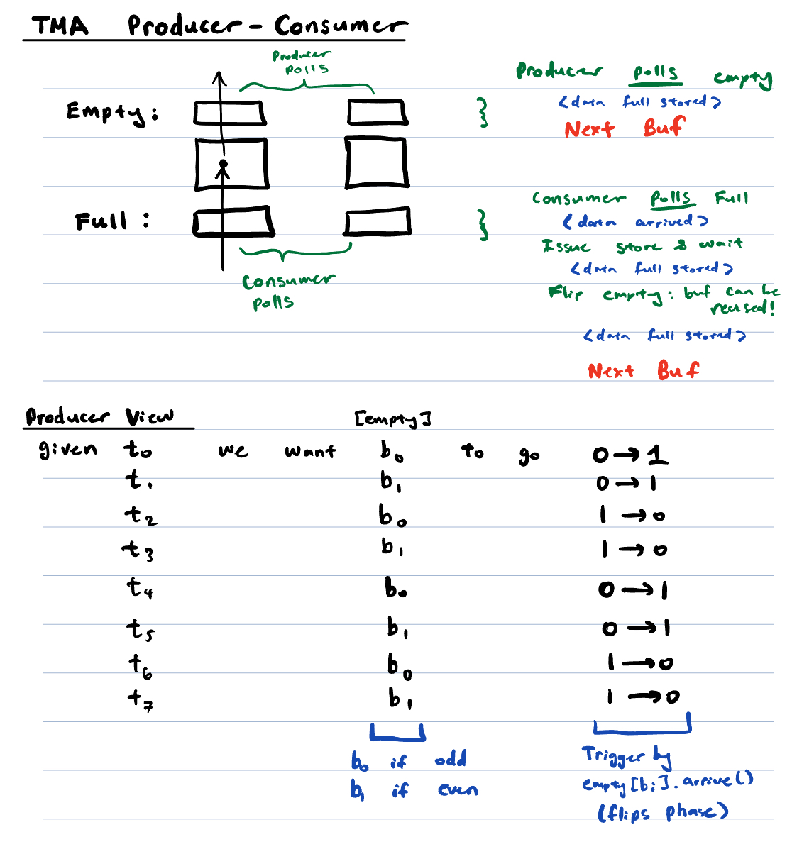
As data flows into the shared memory buffer, the “full” mbarrier gets tripped and flips phase. As data flows out of the shared memory buffer, the “empty” mbarrier gets tripped and flips phase. This is why we need 2 mbarriers per shared memory buffer: one to note when the staging buffer is fully filled and another to note when it’s fully drained.
What was especially confusing for me was the fact that the staging buffer index and phase-shift direction can both be computed deterministically from the tile we’re working with. Given tile i, we enforce the rule that it goes through buffer i/2, and its “full” and “empty” mbarriers are meant to wait for either a 0->1 or 1->0 phase shift.
A note on the phase-shift calculation: mbarrier.wait(0) means we only proceed when we phase-shift from 0->1, and .wait(1) means from 1->0. We determine .wait(x), where x = parity(tile_index / 2), i.e. x is 0 when (tile_index/2) is even, and 1 when (tile_index/2) is odd. This was hard to wrap my head around because it’s dependent on the number of staging buffers you have, but hopefully the above diagram makes this more obvious. In any case, the key point is that the phase-shift you’re waiting on is calculated based on the tile index, and the exact computation is even_or_odd(tile_index/2).
This results in the following general code snippet:
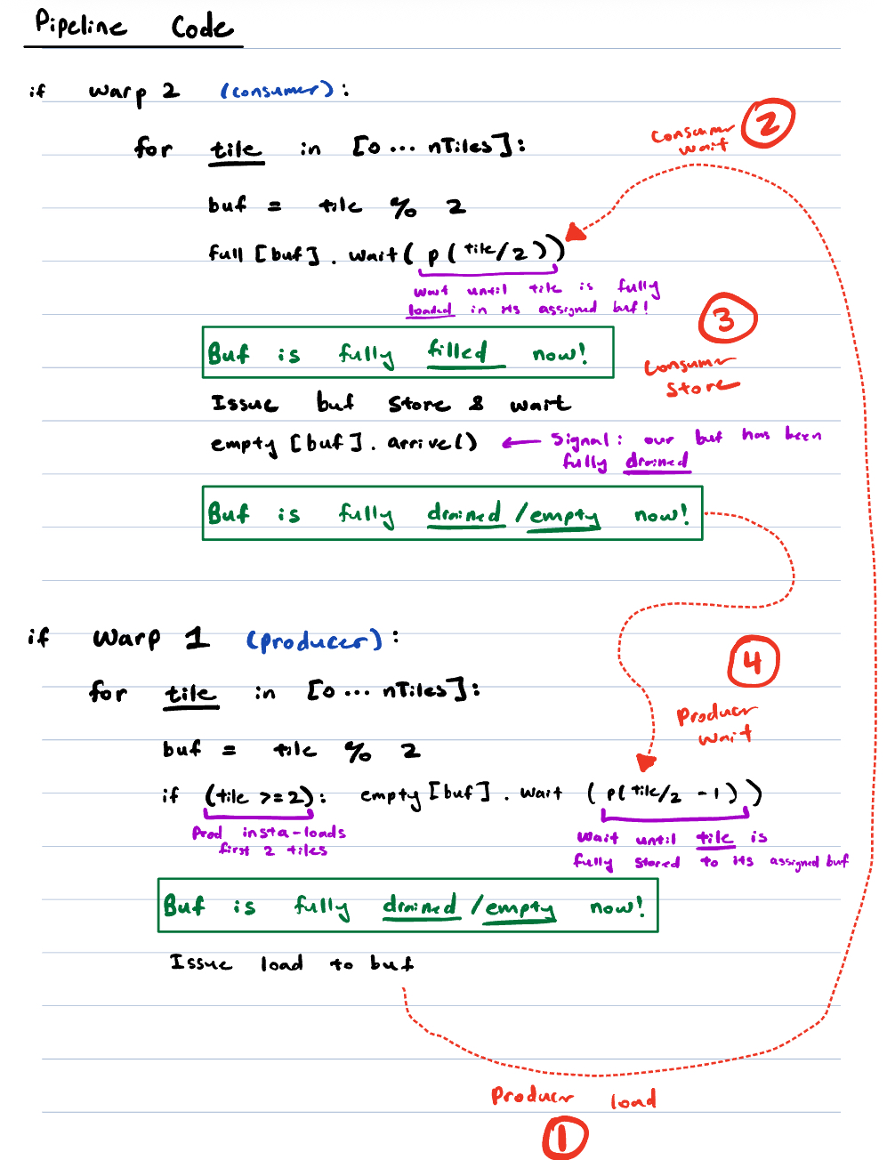
Take the time to really work through it and internalize. At it’s core it’s extremely simple: I labeled in red the most important parts. The producer and consumer each have a wait and store respectively, but the key trick that makes this pipeline work is the phase bit logic above.
This is a dump of my learnings and thoughts after a long night of code analysis - hope you found this useful! Please contribute if you notice anything wrong, and happy cuda programming!